 Upgrading The Network
Network Diagrams & Topoplogies
Showcasing designed blueprints that illustrate the healthcare office’s complex infrastructure, ensuring secure, agile operations & full compliance.
Explore Network Diagrams & Topologies
In this page, we present five distinct diagrams highlighting critical aspects of our upgraded healthcare office network—from physical cabling to logical layers, WAN configurations, cloud integration, and security segmentation. Each topology showcases how Cisco hardware, private/public clouds, and compliance requirements all come together to form a robust infrastructure.
Physical Cabling & Infrastructure Layout
This diagram depicts the physical wiring and connectivity across our small office. It highlights how devices—such as Cisco switches, firewalls, and user endpoints—are physically patched together. By mapping out cable runs and patch panels, we ensure consistent performance, simpler troubleshooting, and organized expansions.
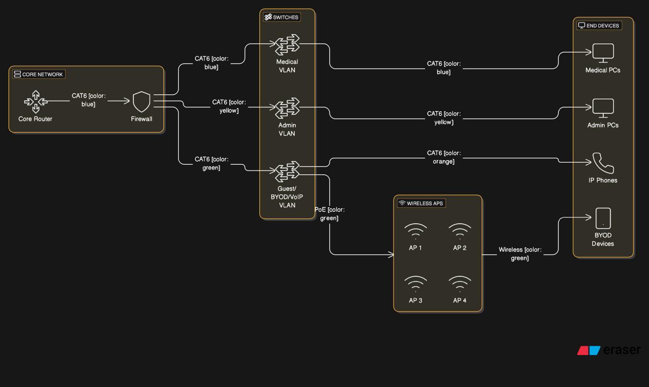
- Categorized cable runs (CAT6 or CAT6A) for gigabit performance.
- Proper labeling & patch panel organization to simplify expansions.
- Rack-mounted Cisco switches & firewall to maximize airflow & reduce clutter.
Logical Network Diagram
The logical diagram represents our IP addressing strategy, VLAN configurations, and key security boundaries. It shows how devices communicate within subnets and the role of RADIUS servers, DNS, DHCP, and domain controllers.
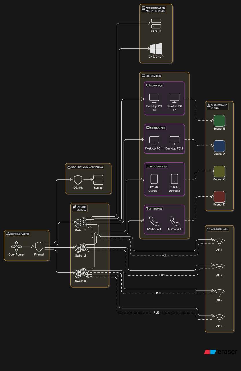
- VLANs isolate sensitive traffic (e.g., medical billing) from general office traffic.
- DNS/DHCP services hosted on Windows Server to handle internal name resolution and dynamic IP assignments.
- RADIUS Authentication ensures each user/device logs in with unique credentials, enabling WPA2-Enterprise Wi-Fi and wired 802.1X.
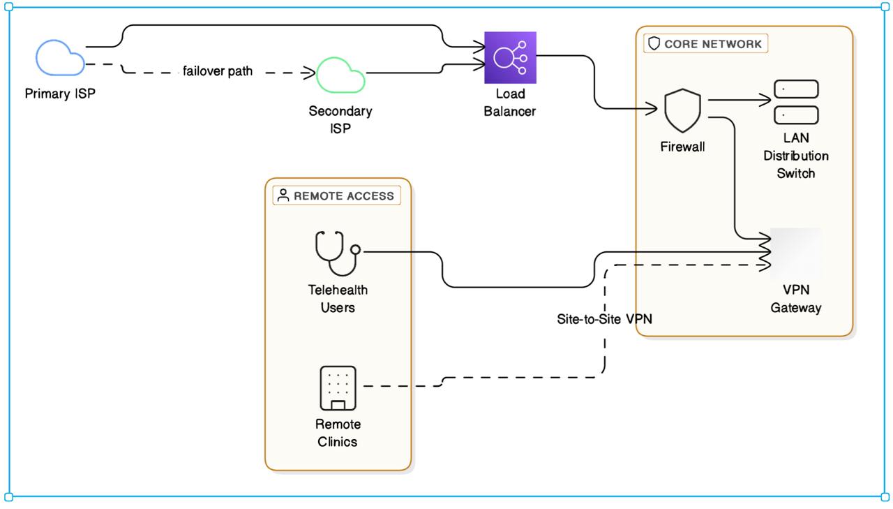
WAN & Remote Access Topology
Here we illustrate the connections to our primary and secondary ISPs, plus remote VPN access for telehealth sessions. With failover and load balancing, we maintain high availability even under adverse conditions.


Security Segmentation & VLAN Architecture
With strict HIPAA requirements, we rely on micro-segmentation and access control lists (ACLs) to limit traffic between critical subnets. This diagram demonstrates how data flows are segmented to isolate PHI (Protected Health Information) from general IT resources, VOIP, and guest wireless.
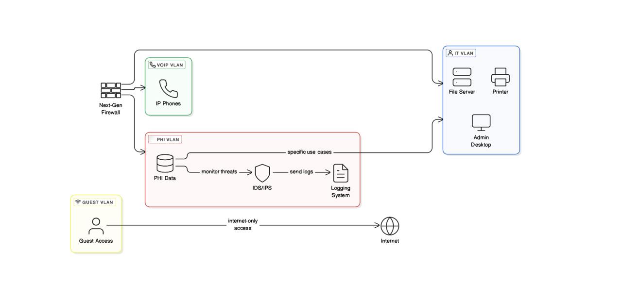
- Inter-VLAN Routing strictly controlled by next-gen firewall rules.
- Zero-Trust ensures no default trust between subnets—access is only granted if explicitly allowed.
- PHI subnet locked down with IDS/IPS monitoring and strict logging.
Hybrid Cloud & Edge Integration
Our final diagram illustrates how on-prem servers integrate with Azure for backups, data replication, and advanced analytics. This approach gives the office the flexibility of public cloud scale, without losing local performance or control.
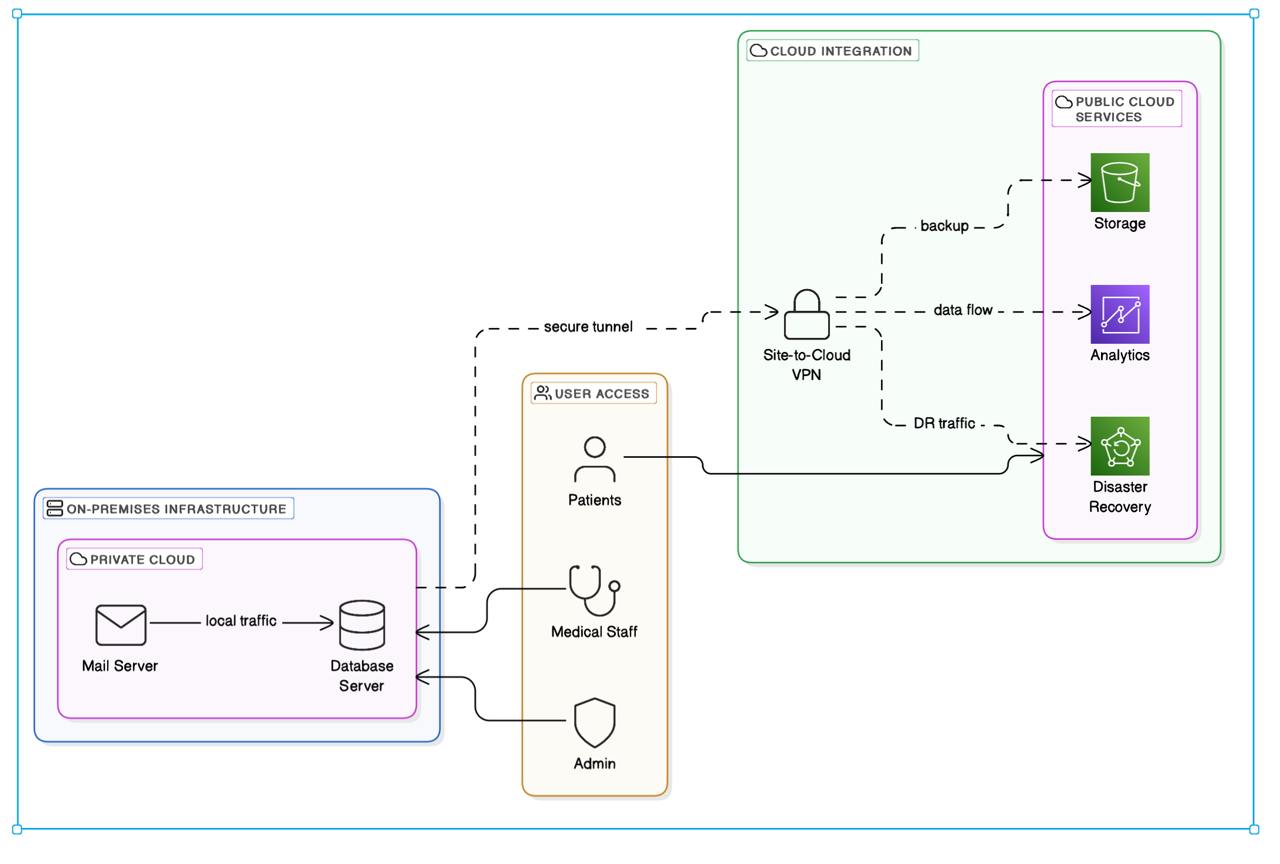
- Private Cloud hosting mail & database servers, stored locally for faster access and full HIPAA compliance.
- Azure Integration for offsite backups, DR (disaster recovery), and threat intelligence services.
- Secure site-to-cloud VPN ensures encrypted traffic between on-prem hosts and Azure endpoints.
Bringing It All Together
With these diagrams, we capture both the physical and logical design of our upgraded healthcare network, from cable management to end-to-end security segmentation. Each topology underscores our commitment to HIPAA compliance, high availability, and operational efficiency. Next, we’ll delve into the specifics of Network Segmentation & Subnetting to further refine and safeguard our environment.